Although unable to make a start on the observatory itself due to having too much other stuff going on in my life, I did want to make a start on at least something related to it. From researching online, I found out that to make a pier adaptor for the concrete pier that I am planning to build, a pair of brake discs could be used as a solution.
Finding the brakes
It turns out that due to a very fortunate coincidence, the geometry of the bottom part of the EQ6-R Pro telescope mount perfectly matches the measurements of certain brake discs. This saves either having to buy a pre-made adaptor (£££), or having to get one custom made (££££).
Although I was able to find quite a lot of example online where other people had successfully turned a pair of brake discs into a pier adaptor suitable to mount into concrete, the one thing that I really struggled to find was which exact discs were required. Browsing various car parts supply websites listed a myriad of options, and the information available about the different sizes was very much lacking.
But, after a number of hours looking I was able to find exactly the right item. To save anyone else the struggle, the details are:
- Manufacturer: Eicher Premium
- Part number: 08.2631.30
- EAN: 5055926315795
- Centering Diamter (this is the key dimension): 65mm
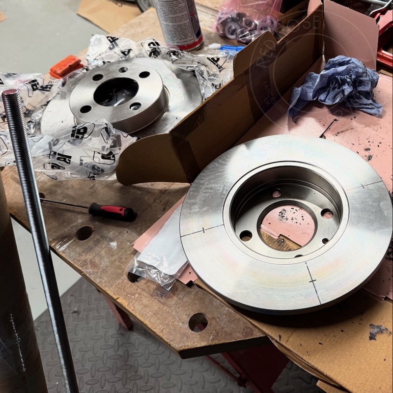
Manufacturing
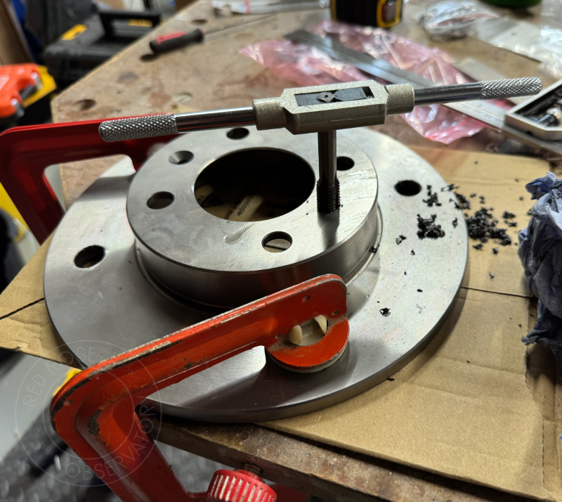
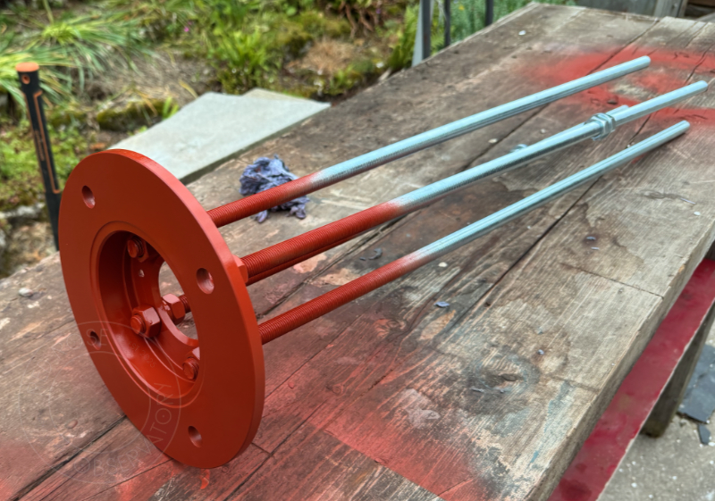
On the one disc (which would act as the bottom part), I used a 16mm Cobalt HSS drill bit (and plenty of cutting/tapping spray) to enlarge the four existing mounting holes at the centre of the disc. These would allow lengths of M16 threaded bar to be bolted in place to extend down below the pier adaptor and be set into the concrete pier below.
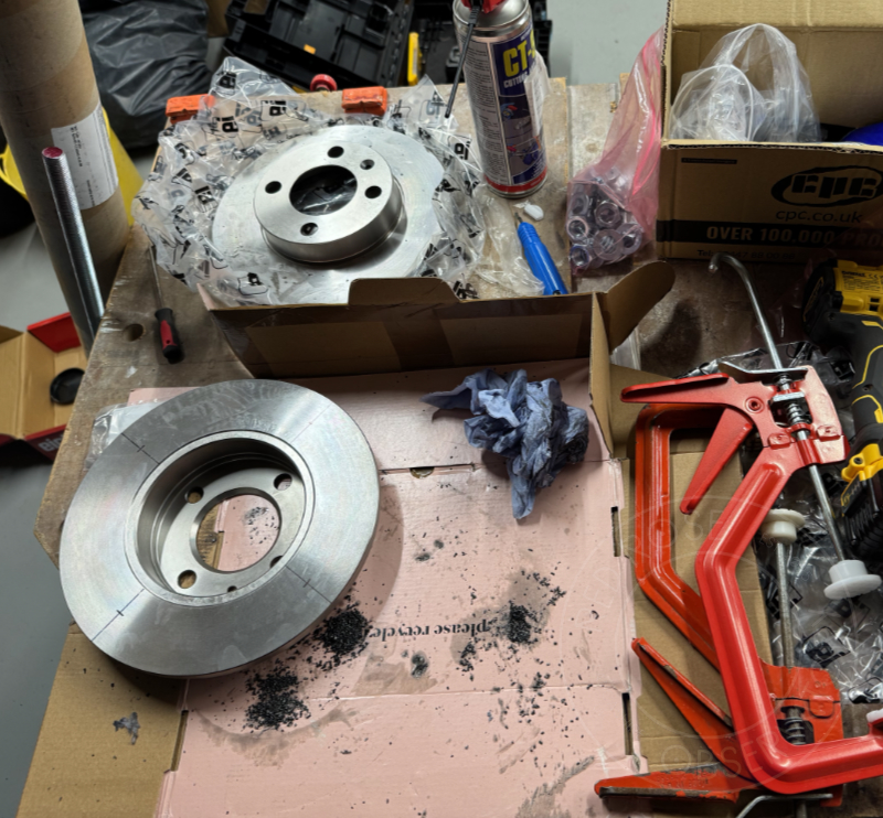
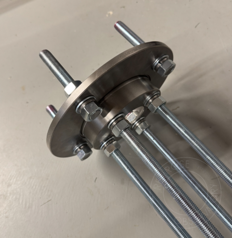
On the braking (outer) surface of both discs, I marked four equally spaced holes, matched between the two discs. These holes would be used with four small lengths of the M16 bar to hold the two discs together. To prevent allowing too much flex, I've tried to keep the gap between the two discs as small as possible, while still allowing enough access to reach in between the two and tighten the bolt holding the mount to the top.
The Azimuth Post
For the disc that would act as the top of the adaptor, this would require a mounting point for the azimuth post. For this, I used my existing mount tripod and measured the exact location of the azimuth post, copying this location onto the brake disc. This hole was then drilled out and suitably tapped. Not wanting to remove and use the azimuth post from my tripod, I instead bolted a M12 bolt through this hole from the bottom so that it protruded an appropriate amount from the top of the disc. I then filed the protruding part of the bolt down using a file to make it match the square shape of the Skywatcher tripod one. Although it doesn't look the prettiest, it's more than adequate as a DIY azimuth post.
Making it pretty
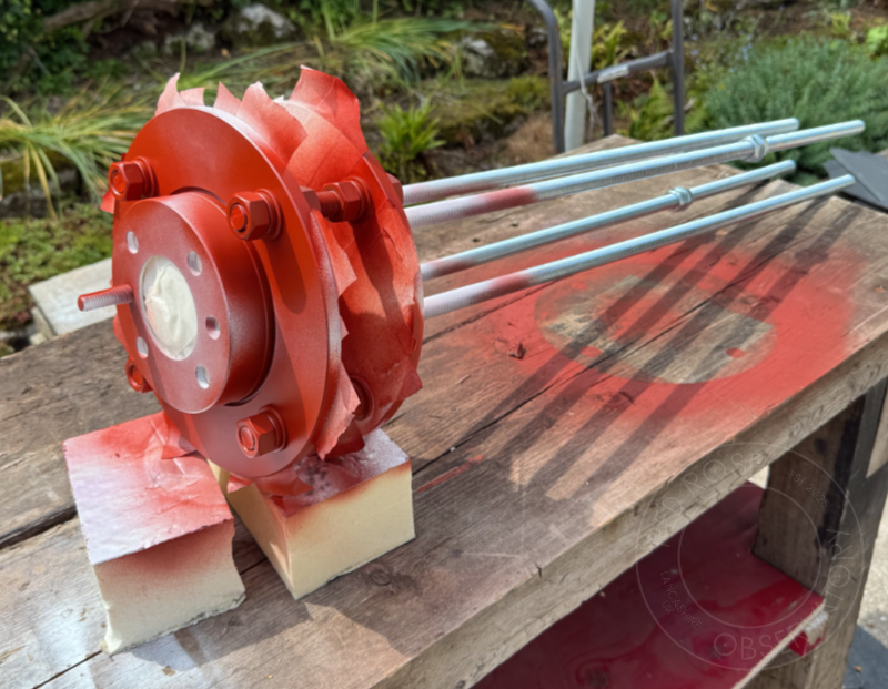
With all of the individual parts now fabricated, everything was thoroughly cleaned with degreaser and then sprayed with red oxide primer.
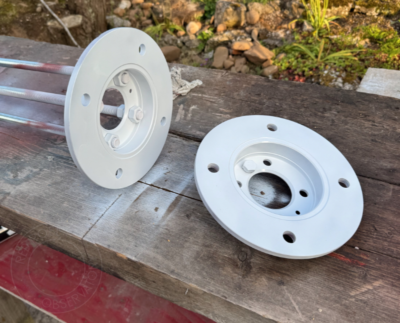
Once primed, the top and bottom halves were painted with a gloss white spray paint (to match the EQ6-R Pro mount) and then given a top coat of clear laquer for added protection. Keeping the two parts separate for painting allowed for easy access to the centre parts, which would have been very difficult to paint properly if the mount were fully assembled.
All that was left was to assemble the two parts together and then give the extra mounting hardware a similar paintjob.
Ready for use
With all that metalwork, the pier adaptor is already quite a heavy bit of kit. It gives me hope that once it's set into the concrete pier, this thing won't be moving anywhere. After propping up the adaptor using a workbench and testing it with the EQ6-R Pro mount, I can confirm it fits ok! The only thing that I might add once it's in the observatory is a thin sheet of PTFE to sit between the adaptor and the mount. This should allow for a bit less friction between the two surfaces, making polar alignment a bit easier (although hopefully this will not be a regular occurrence).